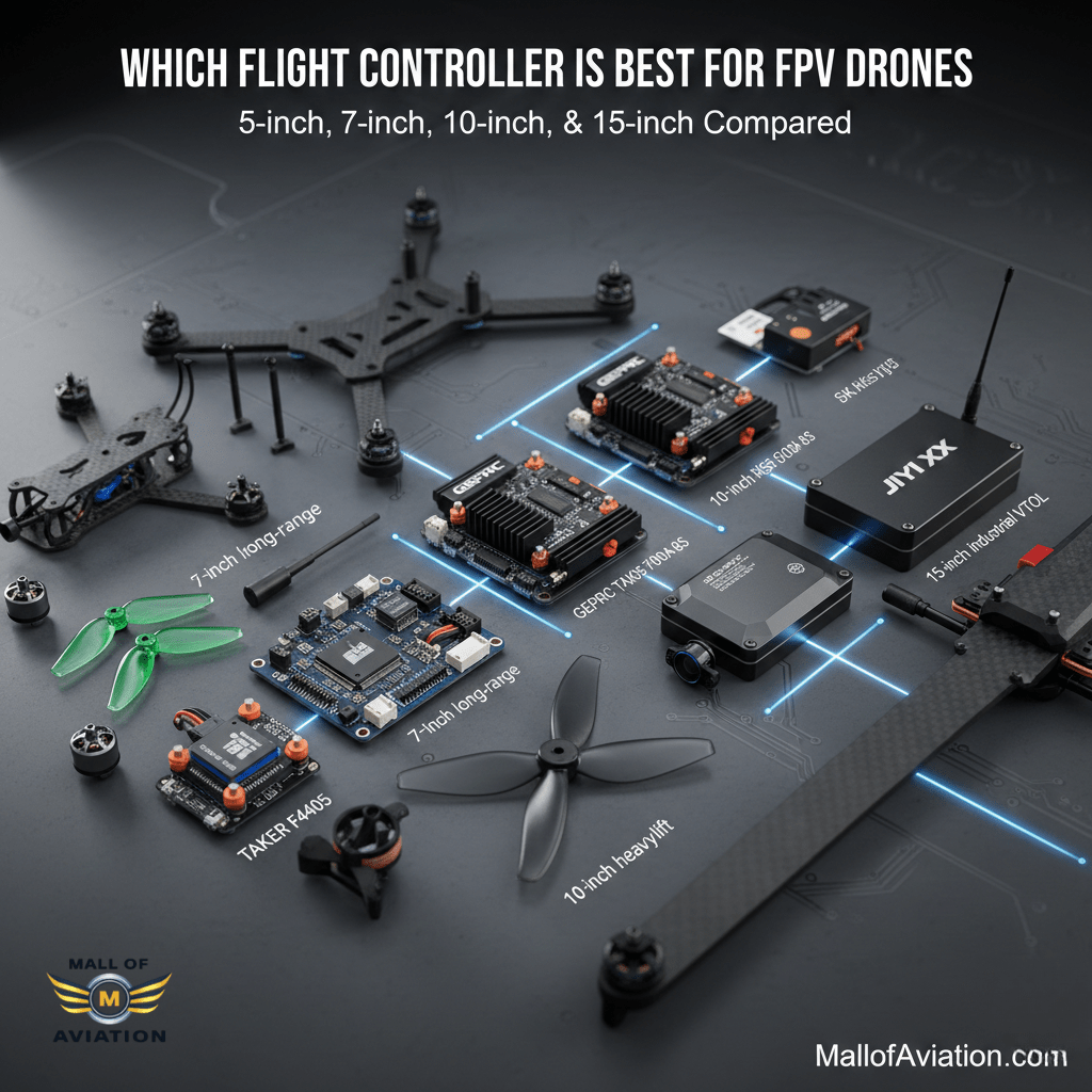
Which Flight Controller is Best For FPV Drones.
1. Introduction: The Dimensional Constraints of Aerial Robotics
In the discipline of aeronautical engineering, every millimeter represents a compromise, and every gram constitutes a penalty. At the Atom Aviation Research & Development Laboratory, we operate under the axiom that the performance of an Unmanned Aerial Vehicle (UAV) is defined not merely by the theoretical maximums of its electronic components, but by the physical integration of those components within the airframe. The Flight Controller (FC) stack—the avionics core comprising the flight control unit and the Electronic Speed Controller (ESC)—sits at the nexus of this design challenge. It is the locus where software intent meets kinetic reality.
This comprehensive research report addresses a critical, often undervalued parameter in the selection of avionics: Size. In the consumer drone market, “size” is frequently reduced to a standardized mounting pattern—typically 30.5mm x 30.5mm or 20mm x 20mm. However, for the R&D engineer, the professional cinelifter pilot, or the long-range endurance specialist, “size” is a multi-dimensional variable encompassing volumetric footprint, vertical clearance (Z-height), component density, thermal mass, and connector accessibility. A stack that fits the mounting holes but obstructs the camera cage, or one that clears the frame but overheats due to insufficient surface area, represents a catastrophic failure of system integration.
We have conducted an exhaustive evaluation of three distinct flight controller stacks currently available within the Mall of Aviation ecosystem. These components were selected not for their similarity, but for their divergence, representing three competing philosophies in avionics design:
-
The Standard-Bearer: GEPRC TAKER F405 BLS 60A V2 Stack.
-
The Heavy-Lift Titan: GEPRC TAKER F405 BLS 100A 8S Stack.
-
The Computational Dense: MicoAir H743v2 70A AM32 Stack.
Through this analysis, which draws upon internal testing protocols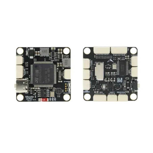 , datasheet deconstruction, and comparative architectural review, we aim to provide a definitive guide to selecting the optimal flight controller based on the physical and electromechanical constraints of your mission.
1.1 The Evolution of Form Factors: From Naza to the Stack
To understand the current state of the art, we must contextualize the evolution of flight controller geometry. In the nascent era of multi-rotors, flight controllers like the DJI Naza or the open-source APM were housed in large, shielded plastic cases, often measuring 50mm x 50mm or larger. These units were modular, requiring separate Power Distribution Boards (PDBs) and standalone ESCs mounted on the arms of the aircraft.
The migration to the “Stack” architecture—where the FC is mounted directly above a 4-in-1 ESC—was driven by the miniquad racing revolution. This consolidation reduced the total wiring harness mass and centralized the Moment of Inertia (MoI), dramatically improving the rotational agility of the aircraft. The industry coalesced around the 30.5mm x 30.5mm mounting standard (derived from the spacing of holes on early 36mm PCBs).
However, as we enter 2026, the demand for power and processing has outpaced the physical space available on a standard 30×30 board.
-
Power Density Paradox: We now demand 100 Amperes of current from a board size that previously struggled to handle 30 Amperes.
-
Processor Real Estate: The transition from STM32F4 to STM32H7 processors requires more supporting passives (capacitors, regulators) and more trace routing for additional UARTs, squeezing the available PCB surface area.
-
Vertical Integration: The introduction of high-definition digital video transmission systems, such as the DJI Air Unit supported by these stacks , has introduced new “Keep-Out Zones” in the Z-axis, forcing stacks to become lower profile even as they become more powerful.
1.2 Defining “Size” in an R&D Context
For the purpose of this report, we define “Size” through four distinct engineering metrics:
-
X-Y Boundary (Footprint): The absolute maximum external dimensions of the PCB. This often exceeds the mounting hole spacing. As we will see with the GEPRC 100A stack, the overhang can be substantial.
-
Z-Axis Stacking Height: The vertical space required effectively. This includes the height of components on the board (inductors, capacitors), the necessary air gap for cooling, and the clearance for connectors.
-
Thermal Surface Area: The effective area available for heat dissipation. In high-current applications, physical size is a proxy for thermal endurance.
-
Integration Volume: The space required for the “loom”—the wiring harness. A compact board with poorly placed pads may require a larger effective volume due to wire routing bend radii.
2. Theoretical Engineering Framework: The Physics of Avionics Sizing
Before dissecting the specific products, it is imperative to establish the theoretical framework that governs why these components are sized the way they are. Understanding the physics allows us to predict performance limitations that are not explicitly stated in the marketing material.
2.1 Thermal Thermodynamics and PCB Surface Area
The most critical constraint on the size of an ESC is heat. The Electronic Speed Controller is essentially a high-speed switching regulator. The MOSFETs (Metal-Oxide-Semiconductor Field-Effect Transistors) rapidly switch current on and off to create the 3-phase AC waveform that drives the brushless motors. This switching generates heat primarily through two mechanisms:
-
Conduction Loss : Determined by the internal resistance of the MOSFET and the current squared
-
Switching Loss : Occurs during the transition between on and off states, proportional to frequency and voltage.
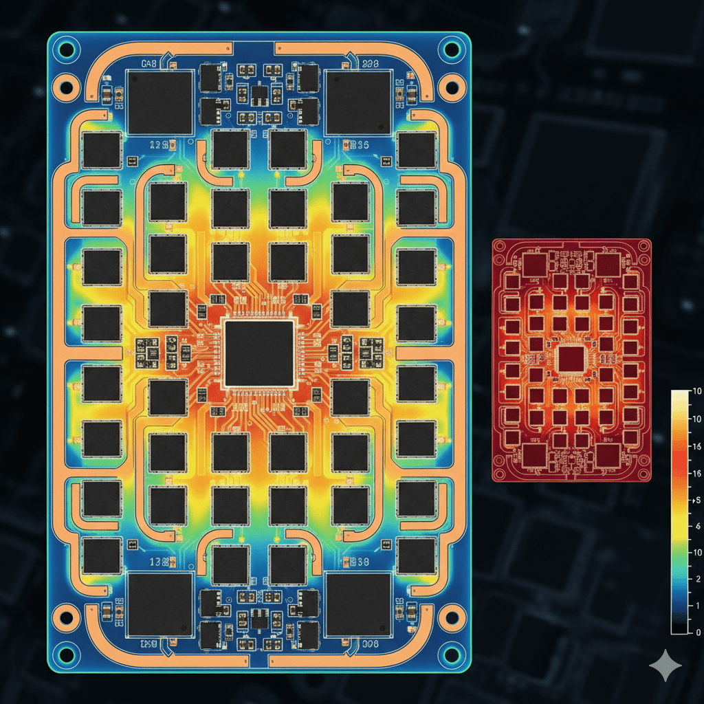
In a flight stack, the PCB itself acts as the primary heatsink. The copper layers within the board spread the heat away from the MOSFET junctions.
-
The Size Implication: A larger PCB provides a larger thermal reservoir and a greater surface area for convective cooling by the prop wash. Reducing the size of a high-current ESC increases the Thermal Current Density. If the heat cannot migrate away from the FETs fast enough, the junction temperature rises, increasing (positive temperature coefficient), which creates a thermal runaway loop leading to failure.
-
Analysis of the 100A Stack: This explains why the GEPRC 100A 8S stack has dimensions of 56.3mm x 61.1mm. It is not merely “oversized”; it is thermally optimized. To handle 100A continuous current without active cooling fans, the designers increased the physical spacing between phases and maximized the copper planes.
2.2 Signal Integrity and Component Density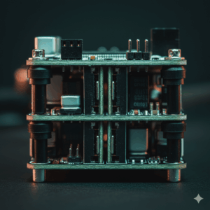
On the Flight Controller (FC) side, the size constraint is governed by signal integrity and routing complexity.
-
Trace Impedance: High-speed signals, such as the SPI bus connecting the Gyro (ICM-42688-P) to the MCU, or the USB data lines, are susceptible to electromagnetic interference (EMI). On a physically smaller board with high component density, traces are forced closer together, increasing crosstalk.
-
Layer Stacking: To maintain a 30×30 footprint while adding features (like the H743’s Dual IMU and 8 UARTs ), engineers must increase the layer count of the PCB (from 4 layers to 6 or 8 layers). This allows signals to be routed on internal layers, shielded by ground planes.
-
Mechanical Resonance: A smaller, denser board is stiffer. A larger board is more flexible. This affects how vibration is transmitted to the gyro. The MicoAir H743, being a dense 36x36mm package , acts as a rigid mass. This requires careful attention to “Soft Mounting” using silicone grommets to decouple high-frequency motor noise from the sensors.
2.3 The “Cube-Square” Law in Avionics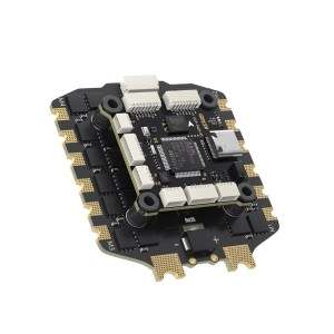
While typically applied to aerodynamics, the square-cube law is relevant here: As we scale up the size of the drone (from 5-inch to 10-inch), the volume (and mass) increases by the cube, while the structural cross-section increases by the square.
-
Implication: A 10-inch drone requires exponentially more power to maintain agility. This necessitates the jump to 8S voltage and 100A current. Consequently, the electronics must grow in size to handle the power. Attempting to run a heavy-lift rig on a “mini” size stack is a violation of these scaling laws and results in immediate component burnout.
3. Product Analysis: GEPRC TAKER F405 BLS 60A V2 Stack
We begin our comparative analysis with the baseline standard for the modern FPV industry. The GEPRC TAKER F405 BLS 60A V2 Stack represents the “Golden Ratio” of size-to-performance for freestyle and racing airframes.
3.1 Physical Architecture and Dimensions
-
Mounting Standard: 30.5mm x 30.5mm (M3 holes).
-
ESC External Dimensions: 42.9mm x 39.7mm.
-
FC External Dimensions: 36.8mm x 36.8mm.
-
Total Weight: ~21.4g (13.7g ESC + 7.7g FC).
R&D Insight:
The dimensions reveal a deliberate asymmetry. The ESC is slightly rectangular (42.9mm width). This extension beyond the square allows GEPRC to place the MOSFETs in a single row per phase along the extended edges, maximizing airflow exposure. However, builders must note that the 39.7mm depth is compact, ensuring the stack does not foul the camera plates in tight “squashed X” frames.
The Flight Controller is strictly confined to a 36.8mm square. This 3.15mm overhang from the mounting holes (30.5mm center-to-center means the holes are at ~15.25mm from center, edge is at 18.4mm) is minimal. This “flush” design is critical for protecting the PCB edges during crashes. In a 5-inch freestyle rig, the stack is often exposed at the sides; keeping the PCB footprint small reduces the likelihood of branch impacts shearing off a capacitor or connector.
3.2 Computational and Sensor Payload
-
MCU: STM32F405 (168 MHz).
-
IMU: ICM-42688-P (via SPI).
-
Blackbox: 16MB Onboard Flash.
Integration Analysis: The F405 is a mature chipset. Its physical package (usually LQFP-64) is manageable. GEPRC has utilized the available board space to integrate a Type-C USB connector. While Type-C is superior for durability, the connector is physically larger than Micro-USB. The 36.8mm board width is necessary to accommodate the through-hole anchorage of the Type-C port, preventing it from ripping off—a common failure point on smaller, “Mini” 20×20 flight controllers.
The inclusion of 16MB of Blackbox memory is a direct result of the board size. Smaller “whoop” style boards often omit the flash chip or use tiny 2MB chips due to space. The 16MB chip (usually a SOIC-8 package) takes up valuable real estate, but on this standard-sized board, it fits comfortably, enabling high-resolution logging (4kHz) for detailed vibration analysis.
3.3 Power Delivery and Wiring
The stack includes a direct connector for the DJI Air Unit. This is a “size-reducing” feature. By integrating the 9V BEC (Battery Eliminator Circuit) and the harness port onto the FC, the builder eliminates the need for an external voltage regulator or messy splice wiring.
-
BEC Specs: 5V 3A and 9V 3A.
-
Size Implication: To provide 9V at 3A (27 Watts), the onboard regulator needs a robust inductor. The 36.8mm x 36.8mm footprint allows for a shielded power inductor, which reduces electrical noise (EMI) radiating into the video feed. Smaller boards often use unshielded chips to save space, resulting in video lines.
Verdict on Size Suitability:
This stack is the “Universal Soldier.” It fits 99% of 5-inch frames (like the GEPRC Mark 5 or ImpulseRC Apex). It balances component spacing (repairability) with compactness. It is the baseline against which all others are measured.
4. Product Analysis: GEPRC TAKER F405 BLS 100A 8S Stack
Moving to the heavy-lift category, the GEPRC TAKER F405 BLS 100A 8S Stack challenges the conventional definitions of “Stack.” It is a component designed for industrial capability, masquerading in a hobbyist form factor.
4.1 The Dimensional anomaly: 56mm x 61mm
This is the most critical data point for the engineer:
-
Mounting: 30.5mm x 30.5mm.
-
ESC External Dimensions: 56.3mm x 61.1mm.
-
Weight: 37.1g (28.8g ESC + 8.3g FC).
R&D Insight:
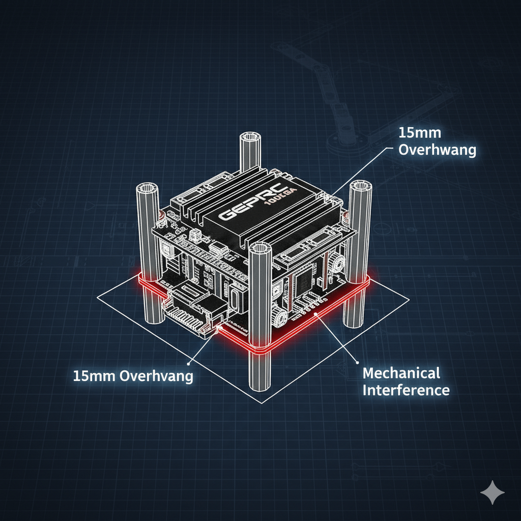
The discrepancy between the mounting holes (30.5mm) and the external dimensions (61.1mm) is massive. There is a 15mm overhang on each side of the mounting screws.
-
Frame Compatibility Warning: In a standard 5-inch freestyle frame, the distance between the front and rear aluminum standoffs is often only 45mm to 50mm. This ESC will not fit inside the main body of a typical racer. It will physically collide with the structural pillars.
-
Intended Airframes: This stack is engineered for “Wide-X” or “Deadcat” 7-inch, 10-inch, and Cinelifter frames (like the GEPRC Cinelog35 Performance or larger Tarot X-series frames ). These frames feature expanded central chassis specifically to accommodate “Over-sized” electronics.
4.2 The “Dual MOS” Architecture
Why is it so big? The snippet references a “Dual MOS design.”
-
Mechanism: To achieve 100A continuous current, the ESC parallels two MOSFETs for every switch position. A 3-phase motor requires 6 switching states (High/Low for phases A, B, C). Standard ESCs use 6 FETs. This ESC uses 12 FETs per motor (or potentially dual-packages, totaling 24-48 power transistors on the board).
-
Thermal Physics: By doubling the semiconductors, the current per device is halved. Since resistive heating is $I^2R$, halving the current reduces the heat in each individual spot by a factor of 4. However, you need physical board space to spread these components out to prevent heat saturation. The 61mm length is a thermal necessity.
-
8S Capability: The move to 8S (33.6V) requires capacitors and FETs with higher voltage ratings (usually 40V or 60V). Higher voltage components are physically larger than their 25V (6S) counterparts due to the thicker dielectric layers required to prevent voltage breakdown.
4.3 Integration in Professional Platforms
The integration of this stack requires a “System Level” approach.
-
Capacitor Bank: The kit includes a large capacitor which must be installed. Due to the board’s size, soldering the capacitor leads requires a high-wattage iron (80W+) because the massive copper planes wick heat away instantly.
-
Connector Access: The larger ESC footprint can obscure the access to the Flight Controller’s USB port if the stack height is low. Builders must ensure the Z-height spacing allows for the USB-C cable to click in fully without hitting the edge of the oversized ESC.
Verdict on Size Suitability:
This is a Specialist Component. It is the best choice for a Cinelifter hauling a RED Komodo or a Long-Range 10-inch mountain surfer. It is unusable for standard 5-inch freestyle due to physical interference.
5. Product Analysis: MicoAir H743v2 70A AM32 Stack
The MicoAir H743v2 70A AM32 Stack represents the “High Density” philosophy. It crams the capabilities of a PX4/Pixhawk autopilot into a standard racer footprint.
5.1 Physical Architecture: The Art of Compression
-
Mounting: 30.5mm x 30.5mm.
-
FC Dimensions: 36mm x 36mm.
-
FC Height: 8mm.
-
ESC Dimensions: Standard (approx 45mm x 45mm based on 70A class norms).
-
Weight: 9g (FC).
R&D Insight:
The 36mm x 36mm footprint is deceptively standard. The marvel lies in the Z-axis (Height). At 8mm tall, the FC is significantly thicker than the GEPRC F405 (which is typically ~5mm).
-
Why the height? The MicoAir unit features a Dual IMU System (BMI088 + BMI270). These sensors are likely mounted on separate daughterboards or foam-isolated platforms within the FC assembly to mechanically decouple them from vibration. This “internal soft mounting” adds height.
-
Installation Hazard: In “Slammed” frames (where the top plate is lowered to reduce drag), there may only be 20mm of total stack height available. If the ESC is 6mm thick, and the FC is 8mm thick, plus 4mm for standoff clearance, you are at 18mm. This leaves very little room for battery straps or VTX mounting on top of the stack. Builders must measure their frame’s vertical clearance carefully.
5.2 The H743 Computational Behemoth
-
MCU: STM32H743VIH6 (480 MHz, 2MB Flash).
-
Interfaces: 8x UARTs, CAN Bus, I2C, SWD.
Density Analysis:
The H743 chip has a massive pin count (usually BGA or LQFP-100). Routing 8 separate UARTs (Universal Asynchronous Receiver-Transmitter) on a 36mm board requires a High-Density Interconnect (HDI) PCB design.
-
Peripheral integration: The availability of a CAN Bus port is a game-changer for size. In traditional builds, GPS, Magnetometer, and Airspeed sensors each require a separate UART wire bundle. With CAN (UAVCAN/DroneCAN), these peripherals can be daisy-chained on a single twisted pair wire. This drastically reduces the “Wire Volume” inside the frame, improving airflow and cooling, effectively mitigating the thermal penalties of a crowded build.
-
Bluetooth Telemetry: The snippet mentions “Integrated Bluetooth”. This eliminates the need for an external Bluetooth module (which takes up space and a UART). This is a prime example of “Virtual Size Reduction”—adding features to the silicon to remove physical components from the frame.
5.3 AM32 32-bit ESC Architecture
The ESC uses AM32 Firmware.
-
Hardware Requirement: AM32 requires a 32-bit MCU on the ESC itself (typically STM32G0 or F0). These chips are physically larger than the 8-bit BB21 chips used in BLHeli_S ESCs (like the GEPRC stacks).
-
Engineering Feat: MicoAir’s ability to fit a 70A power stage AND the larger 32-bit control logic into a standard footprint is impressive. It likely utilizes DirectFET technology or highly integrated Gate Drivers to save space.
Verdict on Size Suitability: This stack is for the Tech-Maximalist. It fits in standard frames (with attention to height) but offers the I/O density of a professional survey drone. It is the only choice for those running ArduPilot or INAV who need GPS, Lidar , and Optical Flow simultaneously.
6. Comparative Synthesis: The Metrics of Choice
To distill this analysis into actionable data, we present a comparative matrix evaluating the stacks against critical R&D criteria.
6.1 Size and Fitment Matrix
| Metric | GEPRC F405 60A V2 | GEPRC F405 100A 8S | MicoAir H743v2 70A |
| Mounting | 30.5 x 30.5 mm | 30.5 x 30.5 mm | 30.5 x 30.5 mm |
| External Footprint | 42.9 x 39.7 mm | 56.3 x 61.1 mm | ~45 x 45 mm (Est) |
| Z-Height Profile | Low | Low | High (8mm FC) |
| Weight (Stack) | ~22g | ~38g | ~25g |
| Frame Compatibility | 5″ Freestyle, Racing | 7-10″ Long Range, X8 | 5-7″ Long Range |
| Wiring Density | Low (Basic Analog/DJI) | Medium (Dual Batter Leads) | High (8 UARTs + CAN) |
6.2 Performance Density Matrix
| Metric | GEPRC F405 60A V2 | GEPRC F405 100A 8S | MicoAir H743v2 70A |
| Amps per mm² | High | Medium (Spread out) | Very High |
| Processing Power | 168 MHz (Standard) | 168 MHz (Standard) | 480 MHz (Extreme) |
| Sensor Redundancy | Single IMU | Single IMU | Dual IMU |
| Voltage Ceiling | 6S (25.2V) | 8S (33.6V) | 6S (up to 8S Li-ion) |
| Firmware Ecosystem | Betaflight | Betaflight | ArduPilot / PX4 / BF |
7. Integration & Best Practices: The R&D Guide to Assembly
Selecting the right size is only the first step. Proper integration is required to ensure reliability.
7.1 Managing the “Keep-Out Zones”
-
For the GEPRC 100A Stack:
The 15mm overhang is a “No-Fly Zone” for standoffs. When mocking up your build, place the ESC on the bottom plate before installing any standoffs to check for clearance. If the ESC touches the aluminum, vibrations will couple directly to the gyro, ruining flight performance. In severe cases, the carbon fiber frame (which is conductive) can short the ESC FETs if the soldermask is scratched.
-
R&D Tip: Apply Kapton tape (polyamide) to the edges of the ESC where it nears the frame standoffs for electrical insulation.
-
-
For the MicoAir H743 Stack:
The 8mm height of the FC means you must be careful with the VTX mounted above it.
-
Thermal Bridging: If a hot VTX (like the Flyto 3W ) touches the top of the FC, it will heat the BMI270 gyro. Gyros drift with temperature. This creates a “lethargic” flight feel. Ensure at least 3mm of air gap between the FC and VTX.
-
7.2 Wiring and Connector Volume
Snippet highlights the MicoAir’s extensive port selection (UARTs, I2C, CAN).
-
The Loom Problem: Utilizing all 8 UARTs creates a massive bundle of wires. In a tight 5-inch build, this bundle can block airflow.
-
Solution: Use 30AWG or 32AWG silicone wire for signals. Twist the wires (Tx/Rx) to reduce magnetic interference and physically compress the loom size. Route wires under the ESC if possible (between the ESC and frame) to keep the inter-stack airflow clean.
7.3 High-Power VTX Integration
The snippet mentions the FLYTO VTX-F2-72, a 3W high-power transmitter with a 30.5×30.5 mounting pattern.
-
Stacking Challenge: Adding this VTX creates a “Triple Stack” (ESC + FC + VTX).
-
Size Math:
-
ESC Height: ~6mm
-
Spacer: 4mm
-
FC Height: ~8mm (MicoAir)
-
Spacer: 4mm
-
VTX Height: ~6mm (Fan included)
-
Total Height: ~28mm.
-
-
Constraint: Most freestyle frames typically have 25mm to 30mm standoffs. This triple stack is a dangerously tight fit.
-
Recommendation: If using the MicoAir H743 and the Flyto 3W VTX, verify your frame has 35mm standoffs. If not, you must mount the VTX in the rear of the frame (not on the stack), which requires longer coaxial cables for the antenna.
8. Second-Order Insights: The Future of Avionics Geometry
Looking beyond the datasheets, we can identify emerging trends in the industry driven by these size constraints.
8.1 The Divergence of “Smart” vs. “Strong”
We are witnessing a bifurcation in board design.
-
The “Strong” Path (GEPRC 100A): Boards are getting larger to handle raw power. The physics of heat dissipation cannot be cheated. As we push for 8S and 12S voltage in hobby-class drones, we will see a return to larger mounting standards (possibly 40mm x 40mm or the resurrection of 45x45mm).
-
The “Smart” Path (MicoAir H743): Boards are maintaining the 30×30 footprint but increasing in layer count and density to support AI, Optical Flow, and Autonomous Navigation. The limiting factor here is no longer the PCB size, but the connector physical size (JST-SH vs JST-GH).
8.2 The Death of the PDB
The snippet mentions a “Martian Mini PDB”. The Power Distribution Board is an extinct species in modern FPV. The integration of the PDB into the ESC (4-in-1) was the first major “Size Reduction” event. The next phase, as seen in the GEPRC stacks, is the integration of the Voltage Regulator (BEC) into the FC, further reducing the component count. We predict the next step will be the integration of the Receiver (ELRS) directly onto the FC PCB, saving yet another UART and external component, as hinted at by the integrated Bluetooth on the MicoAir.
9. Final Recommendations
Based on the rigorous analysis of physical dimensions, thermal capacity, and mission suitability, the Atom Aviation R&D Lab provides the following definitive recommendations:
9.1 The Best All-Rounder for 5-Inch Freestyle
Primary Recommendation: GEPRC TAKER F405 BLS 60A V2 Stack
-
Why: It respects the geometric limits of the standard 5-inch airframe. Its “flush” 36.8mm FC design protects it from damage. The 60A power output is the sweet spot for 6S motors (1700KV-1950KV). It fits comfortably under a standard VTX or DJI O3 Unit.
-
Target Pilot: The Freestyle Ripper, the Bandolero Pilot, the Racer.
9.2 The Only Choice for Heavy-Lift & Cinelifters
Primary Recommendation: GEPRC TAKER F405 BLS 100A 8S Stack
-
Why: It is the only option capable of safely handling the thermal loads of 8S voltage and heavy payloads (Cinema Cameras). Its massive 61mm footprint is a feature, not a bug, providing necessary thermal mass.
-
Warning: Do not attempt to install this in a frame smaller than 7-inch.
-
Target Pilot: The Professional Cinematographer, the Industrial Operator.
-
Link:(https://mallofaviation.com/product/geprc-f405-8s-stack/)
9.3 The Best for Long-Range & Autonomy
Primary Recommendation: MicoAir H743v2 70A AM32 Stack
-
Why: It offers the highest “Compute-to-Size” ratio. For long-range missions where GPS rescue and waypoint navigation are critical, the H7 processor and Dual IMU provide the necessary reliability. Its comprehensive I/O (CAN, I2C) allows for a “Smart Drone” build in a compact package.
-
Target Pilot: The Long-Range Explorer, the ArduPilot Developer, the Tech Enthusiast.
-
Link:(https://mallofaviation.com/product/h743-70a-fpv-stack/)
10. Conclusion
In the high-stakes environment of FPV flight, “One Size Fits All” is a fallacy. The flight controller is the brain, and the ESC is the heart of the aircraft. Selecting them requires a holistic understanding of the organism you are building.
If you are building a nimble fighter jet, choose the compact efficiency of the GEPRC 60A. If you are building a cargo hauler, choose the brute force of the GEPRC 100A. If you are building a supercomputer with wings, choose the MicoAir H743.
Measure twice, solder once, and fly forever.
11. Appendix: Technical Reference Data
11.1 Component Specification Comparison
| Feature | GEPRC F405 60A V2 | GEPRC F405 100A 8S | MicoAir H743v2 70A |
| Price (approx) |
₹7,500 |
₹16,000 |
₹10,999 |
| Processor | STM32F405 | STM32F405 | STM32H743 |
| Gyro | ICM-42688-P | ICM-42688-P | BMI088 + BMI270 |
| Input Voltage | 3-6S | 3-8S | 3-6S (8S Li-ion) |
| Cont. Current | 60A | 100A | 70A |
| ESC Protocol | BLHeli_S (Bluejay Ready) | BLHeli_S (Bluejay Ready) | AM32 (32-bit) |
| Install Dimensions | 30.5×30.5mm | 30.5×30.5mm | 30.5×30.5mm |
| Outer Dimensions | 42.9 x 39.7 mm | 56.3 x 61.1 mm | ~45 x 45 mm |
11.2 Glossary of Terms
-
Stack: A vertical assembly of Flight Controller and ESC.
-
MoI (Moment of Inertia): The resistance of the drone to rotation. Centralizing mass reduces MoI, increasing responsiveness.
-
HDI (High Density Interconnect): A PCB technology allowing for finer lines and more components per square inch.
-
Keep-Out Zone: The physical space around a component that must be kept clear of obstructions to ensure electrical safety and mechanical fit.
-
8S: A battery configuration of 8 cells in series (nominal 29.6V, max 33.6V).
-
Cinelifter: A heavy-duty FPV drone designed to carry cinema-grade cameras (e.g., RED Komodo, BMPCC).